Flat laser-cut features, formed dimensions, welded structures and machined interfaces behave differently. We review each critical characteristic against the proposed route and final function.
Capability Review Factors
Material grade, thickness and temper
Part size, geometry and feature relationships
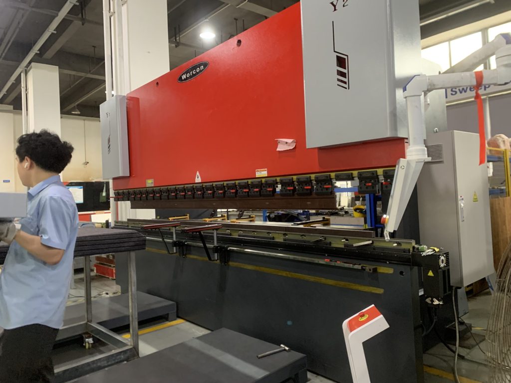
Number and direction of bends
Welding heat input and fixture strategy
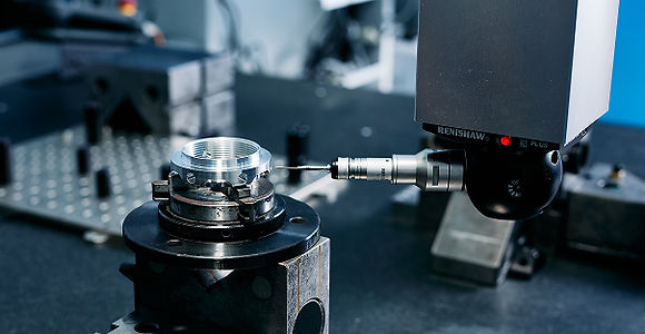
Inspection access, datum and measuring equipment
Tolerance Confirmation Process
Identify critical and noncritical dimensions.
Review cumulative tolerance through forming and assembly.
Match inspection methods to drawing requirements.
Propose machining or fixture control where necessary.
Confirm achievable values for the specific project.
No Fixed Precision Claims
This page is a capability framework rather than a promise of fixed precision. Final tolerances are confirmed only after drawing, material and production-route review.
Discuss Your Drawings and Requirements
Send the drawing, material, quantity and application details for an engineering review and project-specific quotation.